
Description
OPEN TEM CELLS FOR EMC PRE-COMPLIANCE TESTING
Radiated emission tests are typically carried out in anechoic chambers, using antennas to pick up the radiated signals. Due to bandwidth limitations, several antennas are required to cover the complete frequency range. Furthermore, it requires much space and the cost of the equipment for a standard conformant setup is immense.
An engineer of a small or medium size enterprise usually has to rely on his experience and on best practice methods in order to design an EMC compliant product. Nevertheless, it is estimated that > 50% of products fail testing first time around. Anytime an engineer sends a new product for compliance testing, it is a shot in the dark. Failing is very expensive. Not only that re-testing costs are high, but also the project schedule and market introduction gets delayed.
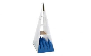
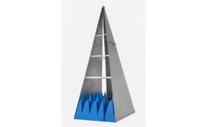
What is needed is an affordable laboratory set up to measure radiated emissions in the own lab, prior to compliance testing. A TEM cell is the right piece of equipment for desktop testing of radiated emissions. Tekbox developed open TEM cells to cover the complete frequency range up to 2GHz and with usability even at frequencies beyond.
Combined with a spectrum analyzer, products can be tested before and after EMC related design modifications. A set up with a TEM cell will not deliver exactly the same quantitative results as a measurement in a certified test house, however it will give an excellent indication on whether the design suffers from excessive radiated noise or not. The engineer will clearly see, whether his changes improved or deteriorated the EMC performance or whether it remained unchanged. Using TEM cells eliminates the guesswork.
A TEM cell is a stripline device for radiated emissions and immunity testing of electronic devices. It is not a replacement, but due to its size and cost it is a convenient alternative to measurements in an anechoic chamber.
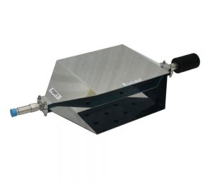
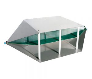
A TEM cell consists of a septum, the conductive strip in the centre section and walls which are connected to ground. The geometry is designed to present a 50Ω stripline. The device under test (DUT) is placed in between the bottom wall and the septum.
The TBTC1/2/3 are so called “open TEM cells”, which got no side walls for convenient placement of the DUT. It may pick up RF background noise, which however can be taken into account by doing a measurement of the cell output signal before powering on the DUT.
Tekbox open TEM cells got a better frequency response compared to standard TEM cells of similar size. TEM cells suffer from higher order wave modes which limit the usable bandwidth. A unique design feature of the Tekbox TEM cells implements resistance perpendicular to the desired propagation direction of the wave. Consequently higher order wave modes and resonances are suppressed.
All TEM cells are supplied together with a 50Ω/25W RF termination, a DC block to protect the spectrum analyzer or RF receiver input and a N-Male to N-Male coaxial cable.
| Specifications | TBTC0 |
|---|---|
| dimension (L x B x H) | 390 x 100 x 62 mm |
| Rectangular area under the septum | 190 x 70 mm |
| Septum height | 28 mm |
| Maximum volume of the test piece (L x B x H) | 114 x 42 x 15 mm |
| Interfaces of TEM-Cell | N-socket |
| Nominal cell impedance | 50 Ω |
| Impedance | 377 Ω |
| Maximum RF input power | 10 W |
| Input reflection factor* S11 | up to 3,15 GHz: < -15 dB |
| Forward transmission factor* S21 (Insertion) | up to 3 GHz: < 3 dB, up to 6 GHz: <4 dB |

Reviews
There are no reviews yet.